6.1 Image Morphing
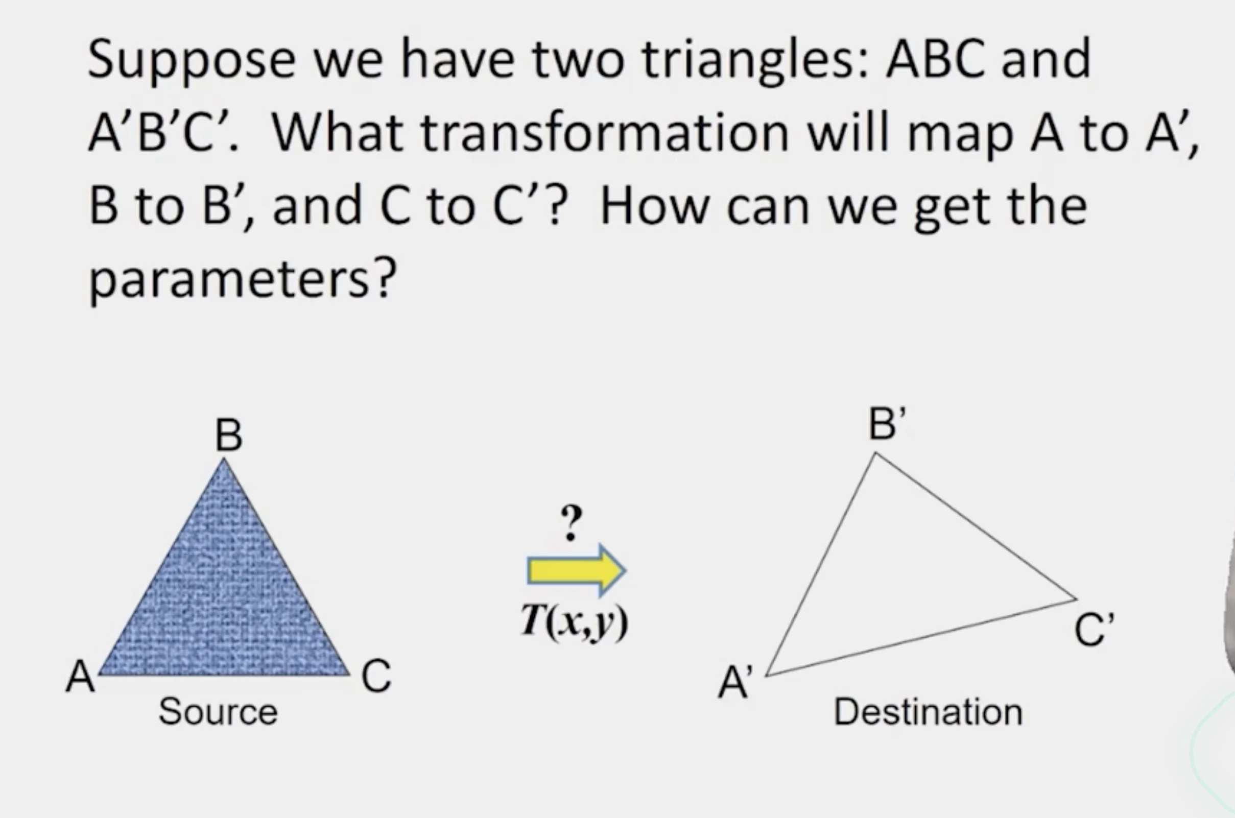
- Affine transformation
Image Morphing
- How do we map intensities from one image to another image
Forward Mapping
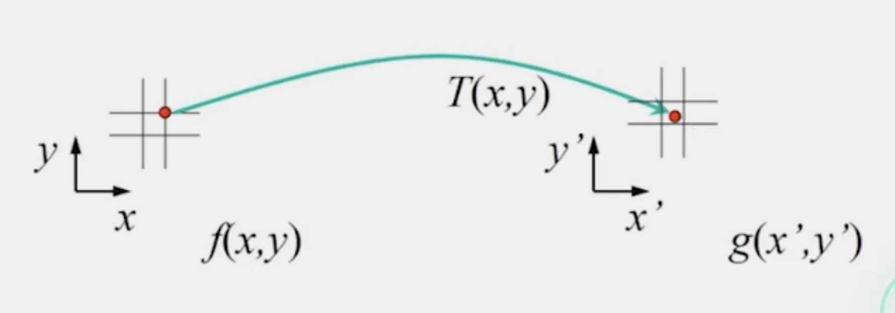
- Send each pixel to its corresponding location in the second image
- Use splatting if the pixel to be transferred lies in between two pixels in the target image
- Distribute color among neighboring pixels
- The neighboring pixels are partly colored with the current pixel
Caution
- You may create a lot of artifacts when the number of pixels is small
- You may have a lot of blank pixels when the number of pixels is large
Inverse Mapping
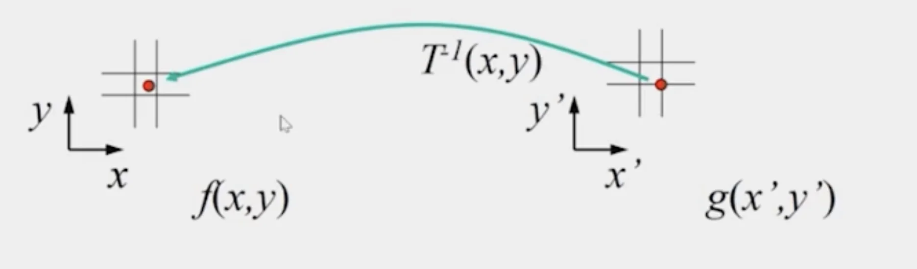
- Find the position in the source image from the target image
- Get each pixel from its corresponding location in the first image
- Use interpolation if the pixel to be transferred lies in between two pixels in the source image
- nearest neighbor
- bilinear
- Gaussian
- bicubic
Bilinear Interpolation
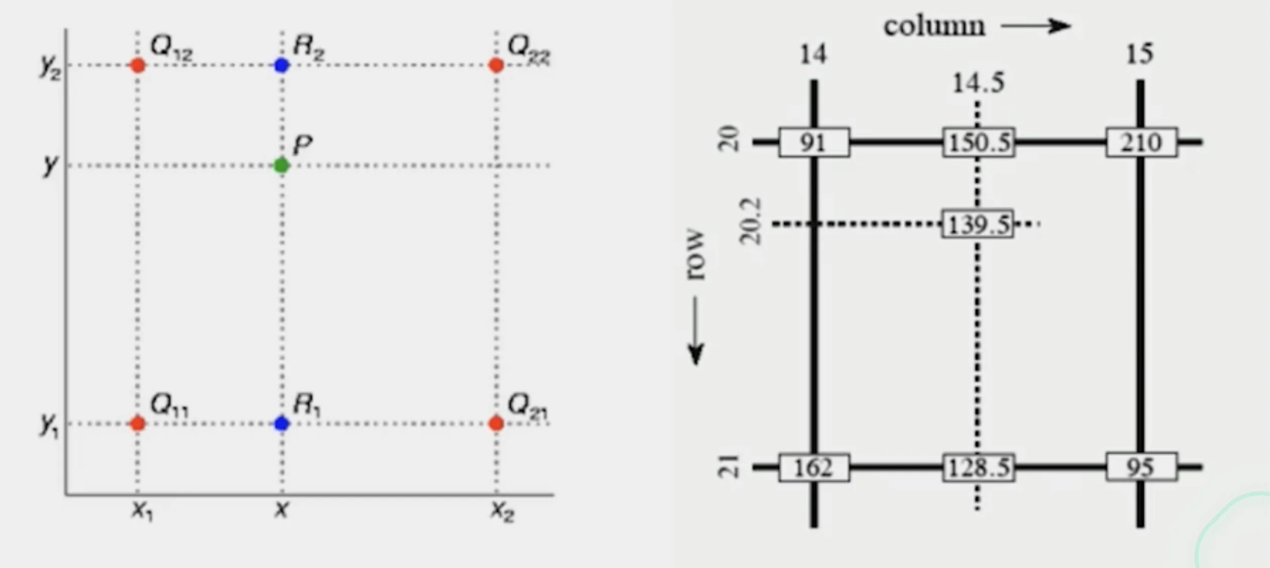
- estimates the pixel value at a non-integer position using the four nearest pixels surrounding it.
- Interpolate along x between each pair of horizontal
- Then interpolate those results along y.
Tip
Usually, inverse mapping eliminates holes; however, it requires invertible warp function
Morphing = Object Averaging
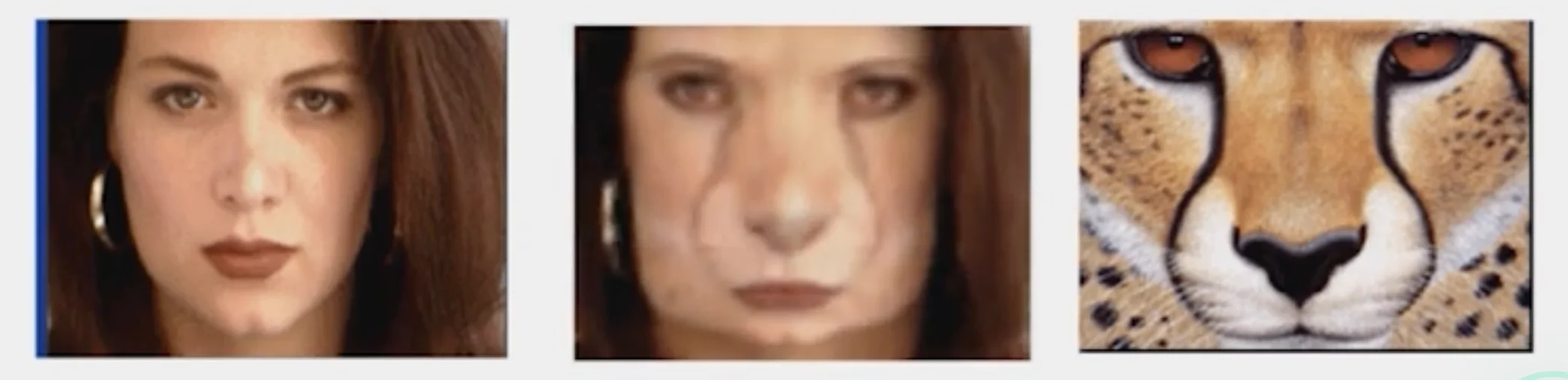
- The aim is to find “an average” between two objects
- NOT an average of two images of objects
- an image of average object
- involves transforming both the coordinates (alignment) and the intensities (texture combination)
- Smooth transition weighted average over time
Averaging Points
- What’s the average of P and Q?
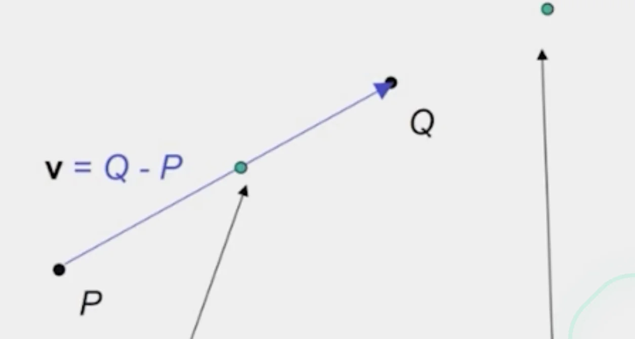
Linear Interpolation
- Given
- New point:
- Or:
- Meaning
- Generate intermediate frames between the source and target
- Effect
- Smoothly blends position and color between two images
Extrapolation
- Given
- New point:
- Or:
- Meaning
- Moving beyond the original range of blending
- Effect
- : extrapolates before the source
- : extrapolate past the target
- Produces exaggerated transformation
Cross-Dissolve
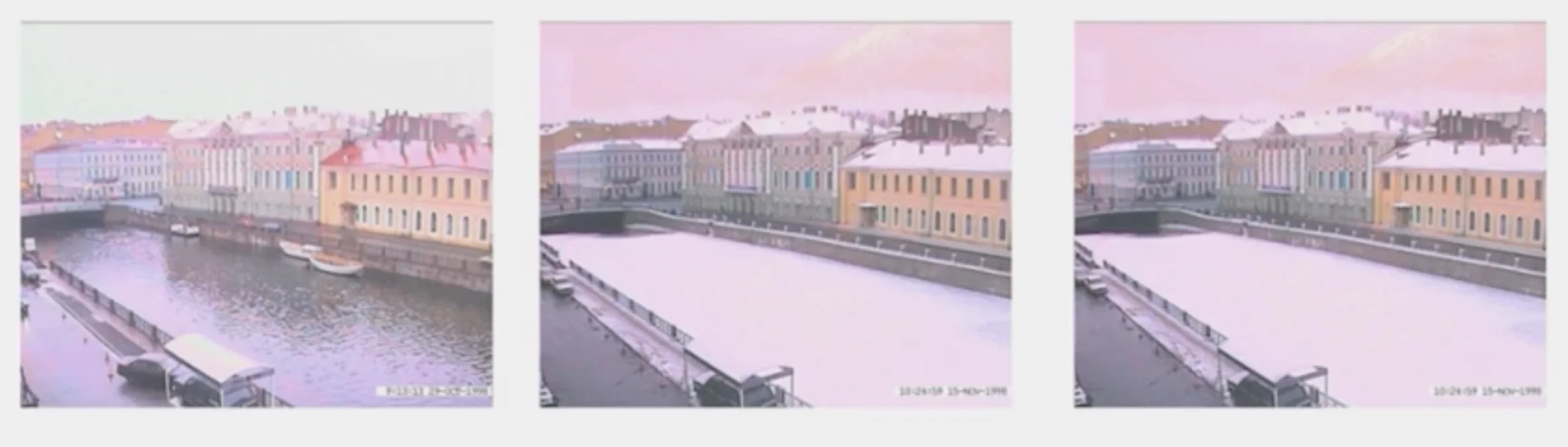
- Interpolate whole images:
- This is called cross-dissolve in film industry
- As long as the change of color values is monotonous, interpolation would work
Important
If the images are not aligned, you need to align them first and then cross-dissolve
Local warp, then cross-dissolve
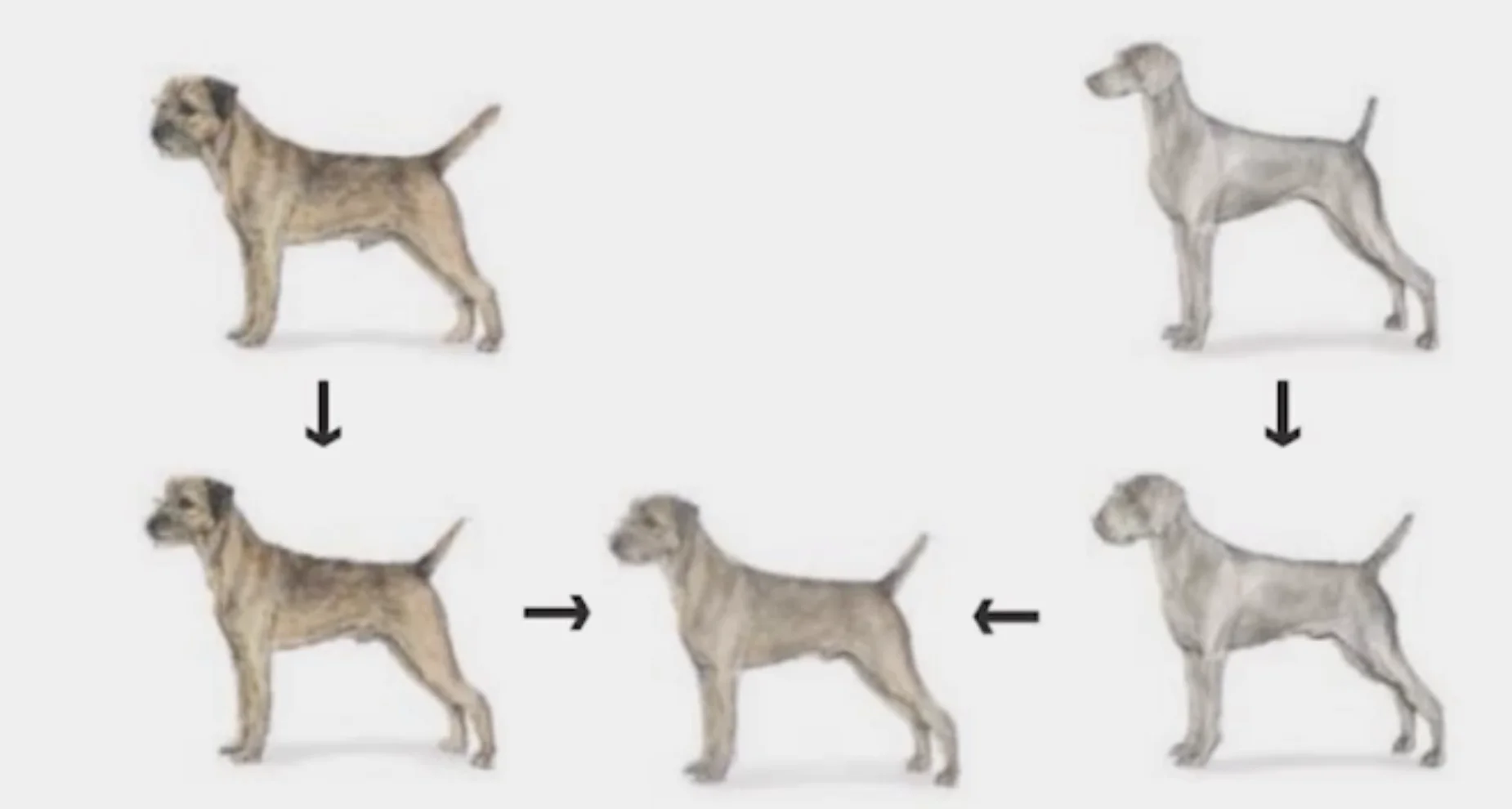
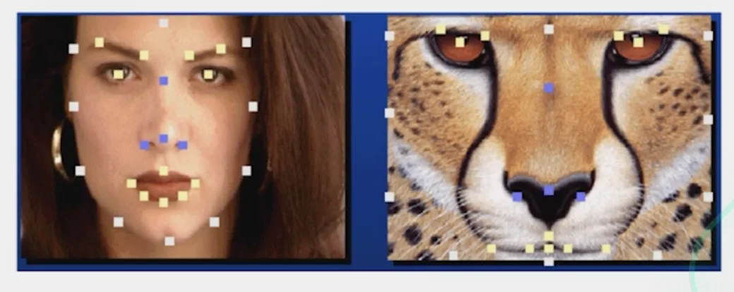
Feature matching
- Nose to nose, tail to tail, etc.
- This is a local (non-parametric) warp
Morphing Procedure
- Find the average shape
- local warping
- Find the average color
- Cross-dissolve the warped images
Warp Specification - dense
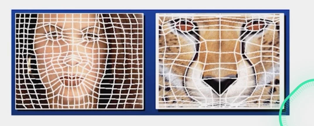
1. Specify corresponding points
2. Triangular Mesh
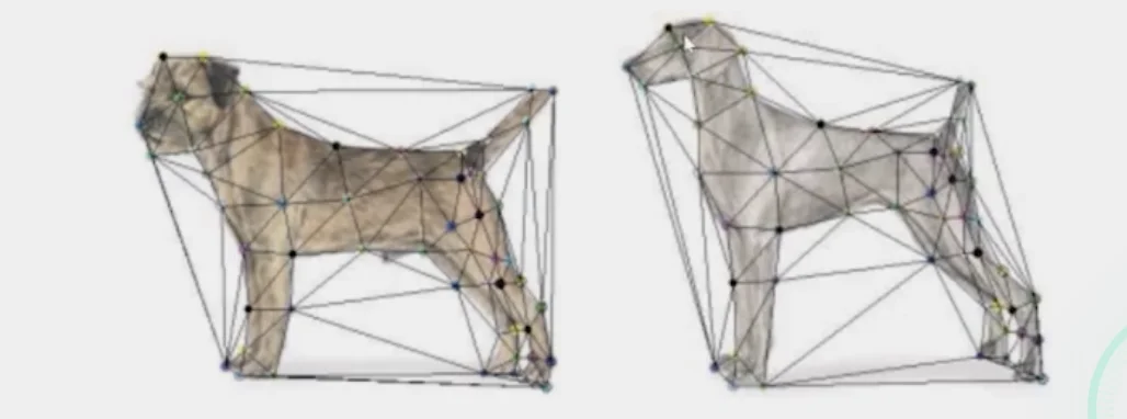
- Define a triangular mesh over the points
- same mesh in both images
- Now we have triangle to triangle correspondences
- Warp each triangle separately from source to target
- Affine warp with three corresponding points
Triangulations
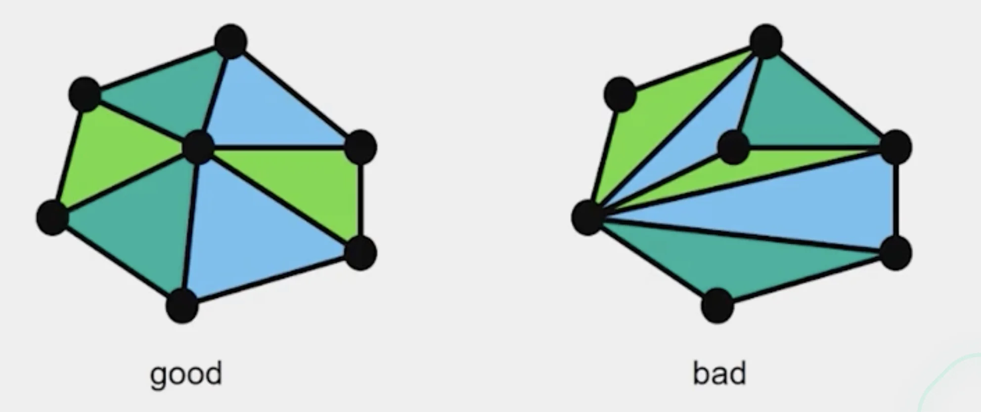
- A partition of the convex hull to triangles whose vertices are the points, and do not contain other points
- Algorithm
Repeat until impossible
1. Select two sites
2. If the dedge connecting them does not intersect previous edges, keep it.- Quality
- A triangulation is better than if the smallest angle of is larger than the smallest angle of
Delaunay Triangulation by Duality
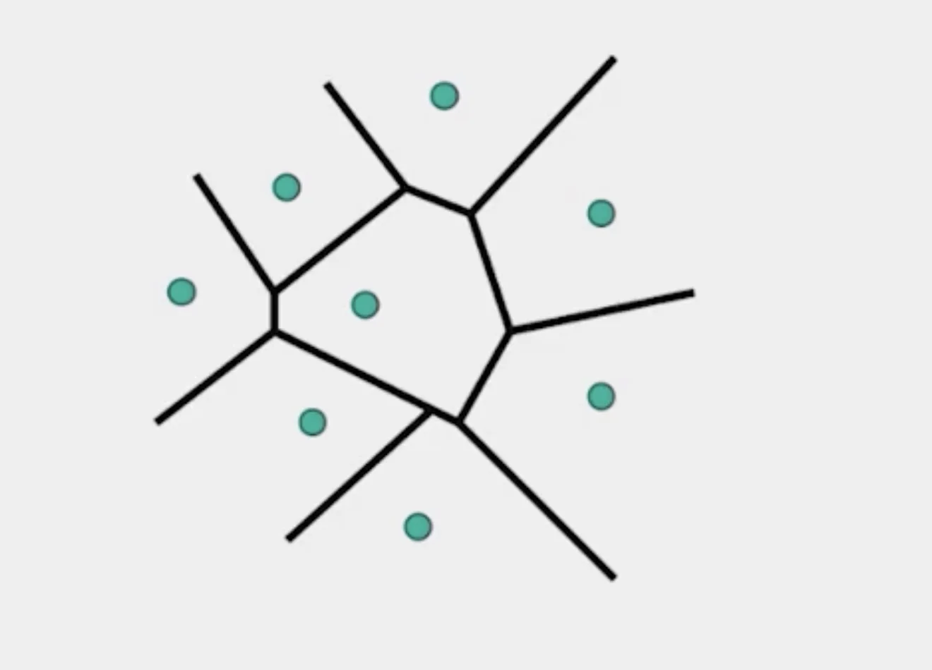
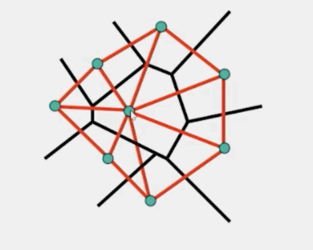
- Draw the dual to the Voronoi diagram by connecting each two neighboring sites in the Voronoi diagram.
- The DT may be constructed in O(nlogn) time
3. Morphing Sequence
3-1. Create an intermediate shape (by interpolation)
- How do we create an intermediate shape at time ?
- Assume
3-2. Warp both images towards it
3-3. Cross-dissolve the colors in the newly warped images
Summary of Morphing
- Define corresponding points
- Define triangulation on points
- Use same triangulation for both images
- For each t = 0:step:1
- Compute the average shape (weighted average of points)
- For each pixel in the triangle, find the corresponding points in each image and set value to the weighted average (warp image toward the average shape)
- Save the image as the next frame of the sequence