Contrast Enhancement
Luminance
- a photometric measure of the phtometric measure of the luminous intensity per unit area of light traveling a given direction
Luminance levesindicate the amount ofluminous powerthat isdetectabletohuman eyesfroma a particular surface and angle of view.
Formulation
- The luminance of a specified point of a light source, in a specified direction, is defined by:
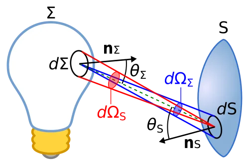
Step 1: What are the symbols?
-
: Radiant flux (power of visible light in photometry, measured in lumens). More generally, in radiometry, is the radiant flux (watts).
-
: An infinitesimal amount of flux, considered with respect to both area and solid angle.
-
(sometimes written ): The surface area element through which radiation is passing.
-
: The differential solid angle subtended by the ray bundle at the surface element. A solid angle is measured in steradians (sr).
-
: The angle between the surface normal of the patch and the incoming (or outgoing) light direction.
-
: A projection factor that accounts for foreshortening. A patch tilted away from the ray captures less flux than one directly facing it.
-
: The luminance (photometric equivalent of radiance). Units:
(candelas per square meter).
Step 2: Meaning of the denominator
-
is the projected area of the surface as “seen” from the light’s direction. This projection ensures that grazing angles collect less light.
-
expresses in which direction the light is traveling (the angular spread of the beam).
So the denominator is:
“the projected area of the patch times the solid angle of the beam.”
Step 3: Putting it together
The formula says:
So luminance (radiance) is the flux density per projected area per unit solid angle.
Step 4: Intuition
- Imagine a tiny surface element .
- Pick a direction at angle .
- Through a tiny cone of solid angle around that direction, some small flux passes.
- The formula says: luminance is the “concentration of flux” in that specific direction per unit projected area.
That’s why luminance (or radiance, in radiometry) is considered directional brightness: it’s not just “how much flux,” but “how much flux in a given direction per surface orientation.”
✅ Summary: This is the definition of luminance (photometric radiance). It relates radiant flux to geometry and direction:
- : how much light leaves/arrives.
- Divided by : accounts for the orientation of the surface.
- Divided by : distributes the flux over angular spread.
That’s why luminance is the fundamental measure of brightness that stays invariant along rays in a lossless medium.
Gamma Correction
- Nonlinear mapping of pixel intensities that adjusts how brightness and contrast are perceived
where:
- input pixel value (normalized to )
- output pixel value
Effect of
Note
This works because our eyes perceive brightness niina nonlinear way. Gamma correction compensates for that and helps adjust images for human viewing
Why does it work?
1. Light vs. Human Perception
- Light intensity is linear. Doubling the number of photons doubles the physical brightness
- Human vision is non-linear as our eyes are more sensitive in dark regions than in bright regions
- A big jump
- Not much of a difference
2. Gamma Mapping
# Draw gamma correction curves for multiple gamma values
import numpy as np
import matplotlib.pyplot as plt

# Input intensity (normalized 0..1)
x = np.linspace(0, 1, 1001)

gammas = [0.3, 0.5, 0.8, 1.0, 1.5, 2.2, 3.0]

plt.figure(figsize=(7, 5))
for g in gammas:
 y = x ** g
 plt.plot(x, y, label=f"γ = {g}")

plt.plot([0, 1], [0, 1], linestyle="--", linewidth=1, label="Linear (γ = 1)")

plt.title("Gamma Correction Curves: Output = Input^γ")
plt.xlabel("Input Intensity (normalized)")
plt.ylabel("Output Intensity (normalized)")
plt.xlim(0, 1)
plt.ylim(0, 1)
plt.grid(True, alpha=0.3)
plt.legend(title="Gamma values", loc="best")
plt.show()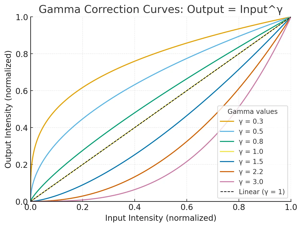
- Curves above the diagonal
- the
outputisgreater thantheinput - Dark pixels are mapped to brighter values
- Curves below the diagonal
- the
outputisless thantheinput - Mid/Bright pixels are pushed down