CH 5.
5-1. Introduction
Caution
It is impossible to access all code and data while keeping memory access fast. Therefore, we need the principle of locality.
What is the principle of locality?
Programs access a small portion of address space at instant time.
- Temporal Locality
- locality in time
- recent accessed addresses may be
re-accessedvery soon - Spatial Locality
- locality in space
- addresses
nearrecent the accessed address may beaccessedvery soon
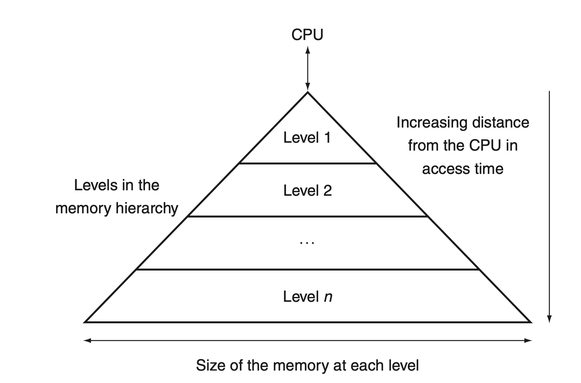
Memory Hierarchy
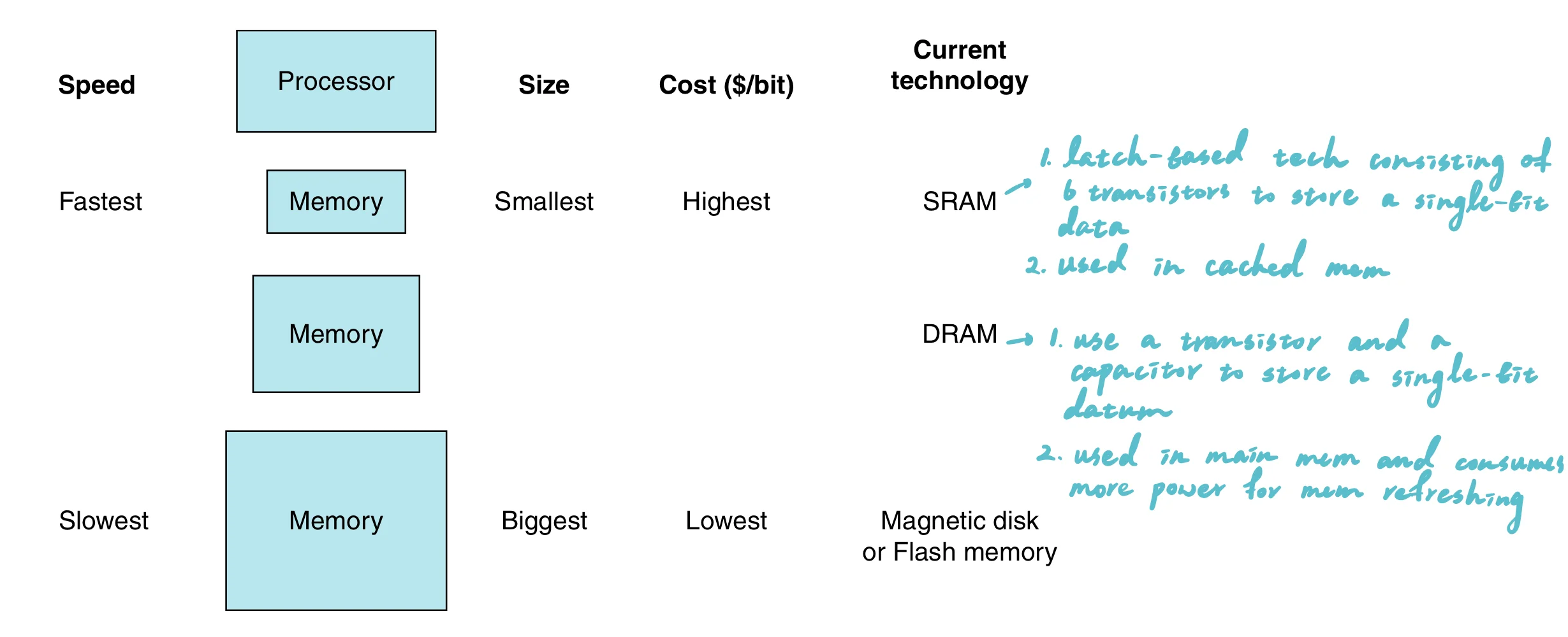
Fastermemory is closer to the processor- Present
as much memory as possiblein the cheapest memory tech
Terminologies
hit: the required address is found in upper level memoryhit rate: the fraction of memory access foundhit time: the time required to access upper level memorymiss: the required address is not found in upper level memorymiss rate: the fraction of memory access not foundmiss penalty: the time to replace upper level memory with required address found in the lower level memory
Note
- Memory hierarchies take advantage of temporal locality.
- Memory hierarchies, such as cache memories, are designed to keep recently accessed data closer to the processor to speed up subsequent accesses.
- On a read, the value returned depends on which blocks are in the cache.
- If the required data is found in the cache (a cache hit), the value is quickly returned from the cache. If it is not in the cache (a cache miss), the memory hierarchy must fetch the data from a lower, slower level (like main memory), and this value is then returned.
- The lowest level of the memory hierarchy usually has the largest capacity.
- This is because slower storage technologies tend to be cheaper per bit stored and are used to store the bulk of the data that does not require fast access speeds.
5.2 Memory Technology
SRAM and DRAM
SRAM (Static Random Access Memory) and DRAM (Dynamic Random Access Memory) are both types of RAM (Random Access Memory), used primarily in computers and other electronic devices for temporary data storage. Here are the key differences between the two:
| Feature | DRAM | SRAM | SDRAM |
|---|---|---|---|
| Full Form | Dynamic Random Access Memory | Static Random Access Memory | Synchronous Dynamic Random Access Memory |
| Speed | Slower than SRAM | Faster than DRAM | Faster than DRAM, synchronized with system bus |
| Cost per Bit | Lower | Higher | Moderate, higher than DRAM but less than SRAM |
| Power Consumption | Higher due to refresh cycles | Lower (no refresh needed) | Moderate, efficient due to synchronization |
| Complexity | Simpler (1 transistor, 1 capacitor per bit) | Complex (6 transistors per bit) | Like DRAM, but includes additional logic for synchronization |
| Usage | Main system memory | Cache memory in CPUs and high-speed storage areas | Main system memory, often used in PCs and servers |
| Density | High | Low | High |
| Volatility | Volatile (needs power to maintain data) | Volatile (needs power to maintain data) | Volatile (needs power to maintain data) |
Hamming Code (SEC/DED)
Overview
The Hamming Code (SEC/DED) is used for error detection and correction, specifically designed to correct single-bit errors and detect double-bit errors in data bits transmitted or stored in computer systems.
Functionality
- Single Error Correction (SEC): Corrects any single-bit error within a block of data.
- Double Error Detection (DED): Detects the presence of two errors within the same block of data.
Mechanism
- Data is encoded with additional bits called parity bits, placed at positions that are powers of two (1, 2, 4, 8,…).
- Each parity bit calculates the parity (even or odd sum) for groups of bits under its coverage. Coverage is determined by the binary representation of the bit positions (e.g., parity bit at position
ncovers all bit positions includingnin their binary form).
Example
Consider a 4-bit data: 1011. To apply Hamming SEC/DED:
- Position Parity Bits: Insert parity bits (
P) at positions 1, 2, and 4.
P1 _ P2 1 P4 0 1 1(P1, P2, P4 are parity bits; underscores show their positions)
- Calculate Parities:
P1covers positions 1, 3, 5, 7 (bits areP1, 1, 0, 1). SetP1to make even parity.P2covers positions 2, 3, 6, 7 (bits areP2, 1, 1, 1). SetP2to make even parity.P4covers positions 4 to 7 (bits areP4, 0, 1, 1). SetP4to make even parity.
- Encoded Data:
- Assuming even parity calculation, encoded sequence might be
0 11 1 0 1 1where0, 1, 1are the calculated parity bits at positions1, 2, 4respectively.
Usage
- Memory Systems: Protects against bit flips in memory chips.
- Data Transmission: Ensures data integrity in noisy communication channels.